This setup uses the VFD 0-10V analog speed input. The Scylla analog spindle output uses the voltage supplied on AVR as its reference, so the VFD 12V_OUT is connected to Scylla AVR and the Scylla output is limited in grblHAL.
The VFD 0-5V input was tested with the VFD 5V_OUT reference, but the Scylla output only reached about 3.63V at S24000. That limited the VFD to about 289Hz, so the 0-10V input is the better setup for this board and VFD combination.
Power off the VFD before wiring. After switching off VFD power, wait at least 10 minutes and verify the DC bus is discharged before touching terminals.
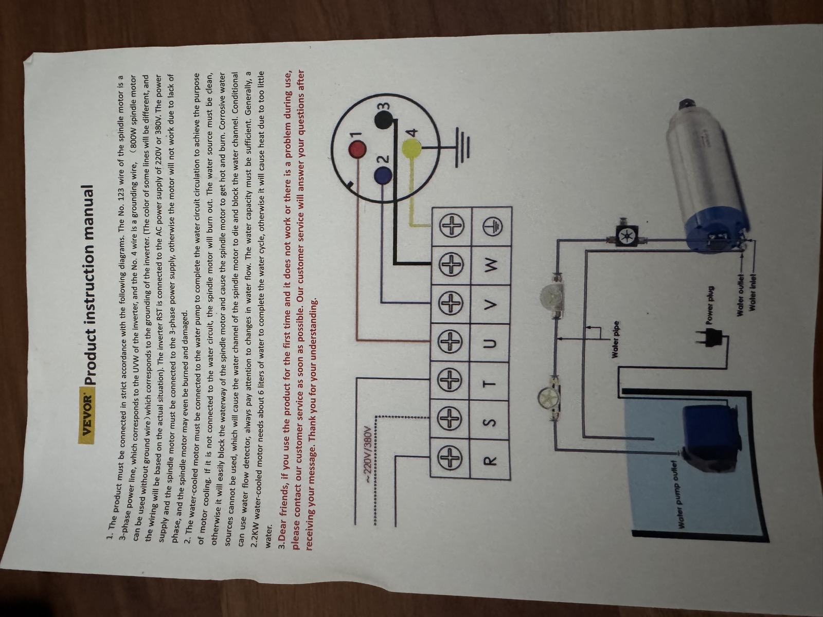
Wire the VFD motor outputs U, V, and W to spindle connector pins 1, 2, and 3, respectively. Connect protective earth to spindle pin 4. If the spindle rotates in the wrong direction, power everything off and swap any two of the U, V, and W connections.
The following pages contain the spindle manufacturer's operating and connector instructions.
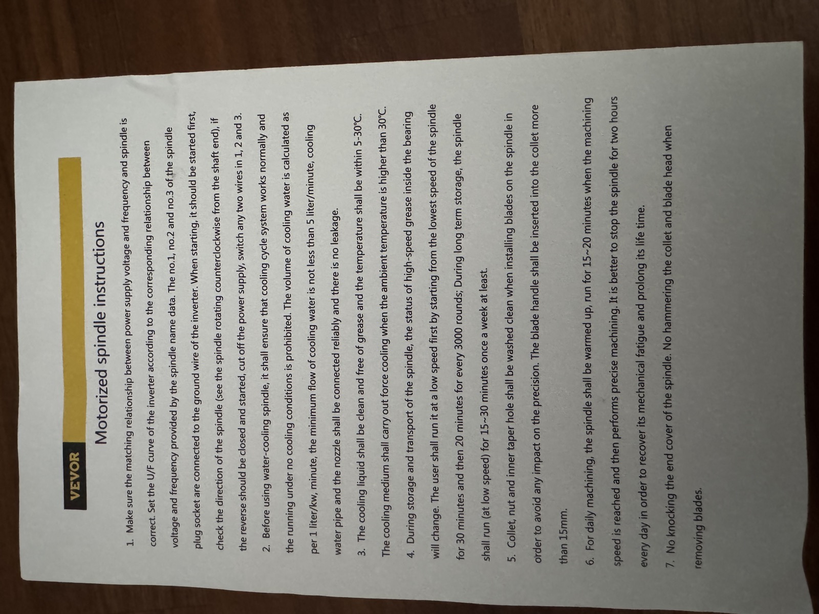
VEVOR spindle instructions, page 1
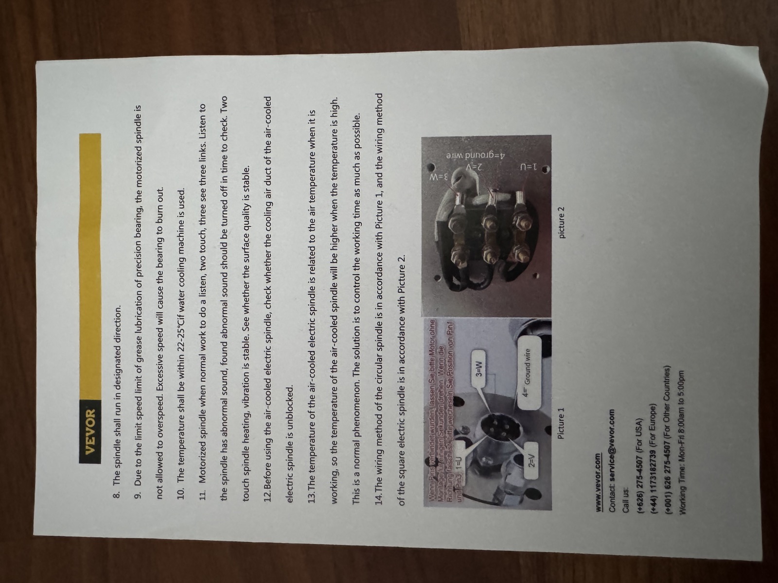
VEVOR spindle instructions, page 2
Set the Scylla jumpers as follows:
| Jumper    | Setting        | Purpose                                                      |
| --------- | -------------- | ------------------------------------------------------------ |
| Speed-OUT | AO             | Select analog spindle speed output instead of digital PWM    |
| SP-GND    | Open initially | Keep analog speed ground and digital control ground separate |
| V-EN      | 12V            | Use SP-EN for VFD run/enable control                         |
| V-DIR     | 12V            | Only needed if SP-DIR is used for reverse selection logic    |
Only install the SP-GND jumper if the VFD behaves incorrectly or its documentation requires analog ground and digital control ground to be common.
Use the Scylla SPIN connector.
| VFD terminal | Scylla SPIN pin |
| ------------ | --------------- |
| 12V_OUT      | AVR             |
| 10V_IN       | SPD             |
| GND          | SP-GND          |
The VFD manual lists 10V_IN as maximum effective voltage 10V, with an absolute maximum of 12V. The tested setup uses grblHAL $36=73 to keep S24000 around 10.0V while still reaching 400Hz on the VFD.
The analog speed signal only tells the VFD what frequency to run at. It does not start the spindle. The VFD still needs a run command.
The VFD FWD and REV inputs are activated by connecting them to VFD GND. For CNC control from the Scylla, keep the VFD configured for external FWD/REV run control, but use only FWD for forward-only operation.
| VFD terminal | Scylla SPIN pin    |
| ------------ | ------------------ |
| control GND  | SP-COM             |
| FWD          | SP-EN              |
| REV          | Leave disconnected |
Do not disable external run control on the VFD for normal CNC use. Setting Pn04 = 1 makes the VFD use the front-panel RUN/STOP button, which is useful for local testing but means M3 and M5 from gSender will not start and stop the spindle.
If the VFD does not run, measure SP-EN to SP-COM while commanding spindle on and off. The VFD expects FWD to be shorted to GND to run. If the behavior is inverted, correct the spindle output inversion in firmware rather than changing wires randomly.
Do not wire FWD and REV directly to SP-EN and SP-DIR. The VFD expects separate low-active direction inputs, while the Scylla provides enable and direction outputs.
For bidirectional operation, use an interposing relay or logic stage:
| Function           | Connection              |
| ------------------ | ----------------------- |
| VFD GND            | Scylla SP-COM           |
| Scylla SP-EN       | Run/enable signal       |
| Scylla SP-DIR      | Relay or logic selector |
| Selector NC output | VFD FWD                 |
| Selector NO output | VFD REV                 |
Ensure the relay or logic prevents FWD and REV from being active at the same time.
Enable parameter editing first:
Pn32 = 1
Configure external 0-10V speed control and external run control:
Pn03 = 4
Pn04 = 2
Pn03 = 4 selects speed from the external 0-10V analog input. Pn04 = 2 keeps run/stop controlled by the external FWD/REV terminals, which is required for gSender M3 and M5 control.
For forward-only operation:
Pn05 = 1
This disables reverse operation. Use only the VFD FWD terminal and leave REV disconnected.
For bidirectional operation with proper relay or logic selection:
Pn05 = 3
Recommended stop and restart behavior:
Pn06 = 2
Pn07 = 1
For the 400Hz CNC spindle:
Pn10 = 400.00
Pn12 = 400.00
Set acceleration and deceleration conservatively at first:
Pn08 = acceleration time
Pn09 = deceleration time
Set the minimum frequency as appropriate for the spindle:
Pn11 = minimum frequency
Use these spindle settings for the 8000-24000 rpm, 400Hz spindle:
$30=24000
$31=0
$33=5000
$34=0
$35=0
$36=73
$36=73 limits the Scylla analog output when using the VFD 12V_OUT reference. With this value, the tested output was about 10.0V at S24000, which made the VFD reach 400Hz while staying below the 12V absolute maximum for 10V_IN.
In gSender, set the spindle range to:
| Setting | Value |
| ------- | ----- |
| Min RPM | 8000  |
| Max RPM | 24000 |
After wiring and configuration, test with a low spindle command first. Confirm that:
FWD and REV are never active at the same time.Tested results with $36=75:
| Command  | Measured SPD to SP-GND | VFD display |
| -------- | ---------------------- | ----------- |
| M3 S8000 | 3.3V                   | 133Hz       |
| S12000   | 5.0V                   | 200Hz       |
| S24000   | 10.0V                  | 400Hz       |
Expected ideal frequencies are about 133Hz, 200Hz, and 400Hz. The tested values are close enough for the current setup.